Other Projects

L-Match Unit

Home-brewed Parallel Plate Capacitor and Inductor for L Matching Unit

1000+  already viewed!

Article Summary

This is about my attempt to design a matching network for my 160m, inverted L using already available parts in the junk box.

Article Highlights

Kamal Edirisinghe
4S7AB / KA5MAL

Author Aug 2005

Having More than 35 years of experience in the Field of Amateur Radio, I have published many articles in prestigious international publications like, QST, CQ-DL, NCJ, Six-News etc.. Here in this web site, these write-ups are intended to give you knowledge about my designs and projects related to the hobby. The articles about foreign HAM activities are intended to share my experience.

I was planning to build a ATU for feeding my 160m inverted L. The design goals were that; 

  • Can tune the complex impedances of 40 + 200j to 50 Ohms
  • Can handle about 500W of power
  • Non corrosive material
  • Outdoor installation in 35C and RH 90% in worse case
  • Cassis grounded

I have asked some of my colleagues to look into their surplus boxes and give me a parallel plate capacitor suitable for the purpose. The plate gap should be around 3mm and capacitance should be around 500pf maximum. I couldn’t find a suitable one even though many hams offered to help. Therefore I thought of home brewing a parallel plate variable capacitor for my specifications.

Since I already had a commercially made variable capacitor with Aluminum plates, I have decided to take the plates from it. Reason is that these plates are made with smooth edges to prevent the sparks from the edges.

The Schematic of the L network tuner given in ON4UN’s Low Band Dxing book. This book has a lot of information for the experimenters..

After carefully opening the commercial capacitor, I was able to remove the plates without too much damage.

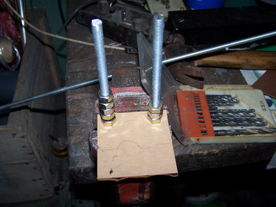
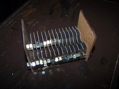
Two separate perspecs sheets of 2.5mm were prepared to hold the thread bar as given in the picture. The 6mm thread bars were attached to one plate both parallel to each other. Careful drilling of holes is required otherwise, it is difficult to fix the parallel plates to the thread bars.

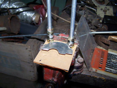
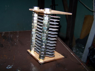
The Fixed parallel plates were attached one by one to the thread bars using 6mm nuts. Extreme care should be taken not to over tighten these nuts. Otherwise the very thin Aluminum plates can be broken easily. I have broken 2 of those 🙁


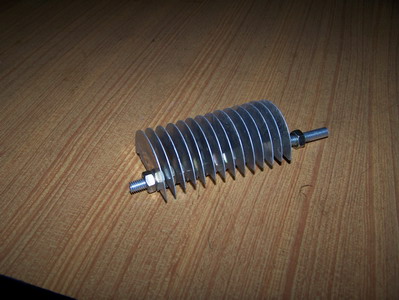
The final assembly of the plates look like below It had 14 plates which should give about 400pf capacitance according to my calculations. But later I found that this gives only about 350pf. Maybe the overlapping is not 100%. The separation is also not uniform. Welcome to the world of home brewing !.

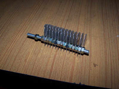
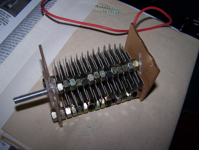
Then the moving plates were also fixed to another thread bar. This thread bar is about 1″ longer than the others since this has to come out of the assembly and get connected to a knob for tuning.

What I learnt from the capacitor construction

It is not easy to obtain the calculated capacitnace due to many factors

It would have been better if I didn’t assemble the border plates closer to the plastic plate. If I did so, it would have been easier to align the mechanical movements of the capacitor. Rather than using many plates of smaller size, it would have been better to use few plates of larger size. Then again the alignment would have been easier (or maybe not ?)

Try to use higher separation of plates and more area of overlapping.

The Construction of the Inductor was not a magic. I had an old single pole 6 way switch removed from some old junk. This was perfect for 6 tappings of the coil . The coil was wound on a PVC 4cm diameter piece of pipe using 18 SWG enameled copper wire. The coil dimensions were calculated using the formulas given in the ARRL handbook. I don’t have inductance measurement equipment so I didn’t bother to verify the design. It works at my power levels, so it is good enough for me for the moment.

The Final matching unit was constructed on a homebrew Aluminum box using dead bug style to see the performance. It works fine with my inverted L and also with the T-loaded vertical for 160m . So the next phase is to water seal the box and place near the feed point of the antenna. I am sorry for not having pictures beyond this point.

73 es Good home brewing