160m T-Wire Antenna
160m Top Band Top loaded, Bottom Fed ‘Swinging’ T-Antenna
1000+ already viewed!
Article Summary
I had a desire for a long time to come up on top bands. The space limitations I had in my home QTH plus the rumors I have heard about the need to have many many radials for verticals on 160m, pushed the project backwards.
Article Highlights
- Design of T-Wire Top Loading
- Feeding the T-Wire
- SWR Curves

Kamal Edirisinghe
4S7AB / KA5MAL
Author Aug 2005
Having More than 35 years of experience in the Field of Amateur Radio, I have published many articles in prestigious international publications like, QST, CQ-DL, NCJ, Six-News etc.. Here in this web site, these write-ups are intended to give you knowledge about my designs and projects related to the hobby. The articles about foreign HAM activities are intended to share my experience.
- Full Solar Powered Radio Station
- SO2R and Multi-Multi Compatible
- Operate on All Bands/Modes/SATS
- DXCC #61,271
- IOTA AS-003, CQ-22, ITU-41
In 2003, I have managed to put up a 80m dipole and did my first QSO to USA with K5NA Richard. Subsequently, I was able to visit this top class top bander in Texas during my business trip to USA. After seeing Richards antenna farm, I got some great ideas and thought that I would also go on 160m somehow.
At the same time, Richard gifted me a book written by ON4UN about Low band Dxing. This contains lot of useful and practical ideas for beginners and experienced hams. Initially I spoke to some of my local and Dx friends about their experience with inverted L antennas. Then I went for an inverted L but the vertical portion was around 40ft which was not enough. Then the vertical section was too closer to the trees. All in all, the inverted L didn’t give a practically manageable impedance in the feed point.
Feeding
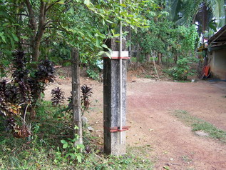
The Feed area of the T-Wire loaded vertical. The 1 1/4 inch bottom aluminum pipe is attached to the concrete structure using brackets.
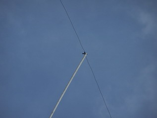
This picture(right) shows the T-wire attachment to the vertical pipe end.
I have been listening on the Inverted L for few days and spoke with Richard again. He advised me to go for a T-wire loaded Vertical and gave me the dimensions of his previous construction.
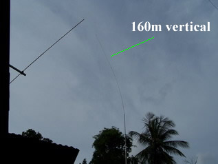
Then I have decided to go with this antenna with an Aluminum tubing vertical section. The idea is to raise the height of the vertical section and prevent the sagging of the horizontal capacitance wires.
Practically, I was able to achieve 53ft of vertical section and 110 ft of horizontal wire. I have used 4, 1/4 wave radials partially buried under ground and achieved about 1.4 SWR around 1830KHz after 18m of coaxial cable . This was good enough to feed directly with 50 Ohm coax and start calling CQ with barefoot. But the resonance occurred on 1950Khz. Maybe I have to think of a way to lengthen the vertical by another 6%. Please see below for the impedance charts.
During the first day, I was able to work VQ9LA from Diego Garcia, who is not very far from Sri Lanka though. Thereafter I have connected my homebrew ATU to the feed point and obtained perfect match at 1830KHz.
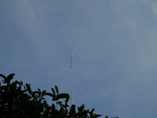
As you can see from the pictures, there is a slight bending of the Aluminum tube from the centre of the vertical section. But the antenna is stable in a very interesting equilibrium. It is nice to watch how this antenna swings in the wind. So, I have named it as 4S7AB’s Swinging T-wire loaded vertical. HI!
Now I am waiting for the band openings on the top band to have some fun. Hopefully in the winter 2005.
Few years later this antenna was dismantled due to the problems in mechnical stability. It was brought down in 2007
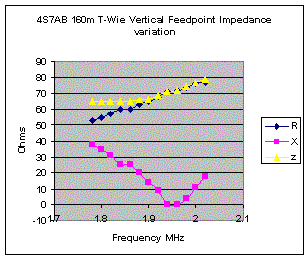
The feed point impedance is around 55-j32 at 1830KHz and is 70 Ohms at resonance (1950KHz). The antenna has to be lengthen by another 4ft to get the resonance to 1.830MHz
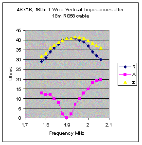
The impedance obtained inside the shack after 18m of cable is much more pleasing due to the SWR variations along the line due to mismatch at the feed point. My rig sees a 1:1.4 SWR on 1.830MHz and a resonance at 1.900 MHz.
