It is assumed that the reader has some basic understanding about this antenna and it’s geometry. If not, a good starting point is to read through G3TXQ Steve’s web site about the ‘Broadband’ version of the Hex beam. K4KIO has a step by step guide for home-brewing the same antenna. There are many others who have written excellent articles about the same subject. Mine is just another one….
The starting dimensions for the 30m element was as given by Steve. But with some NEC modeling and practical Turing, I found that 296″ driven length instead of 306 ” per half element works well in reducing the SWR near 10.11. I may go any cut of 2 – 4 inches more Reflector is 578″ and works fine. I have a 1:1 balun for each element fed with separate coax lines. Sharing the same coax is a nightmare and you can end up hours and hours in the tower tuning the hex with unsatisfied results. So my advise is to use separate coaxes.
The Dimensions
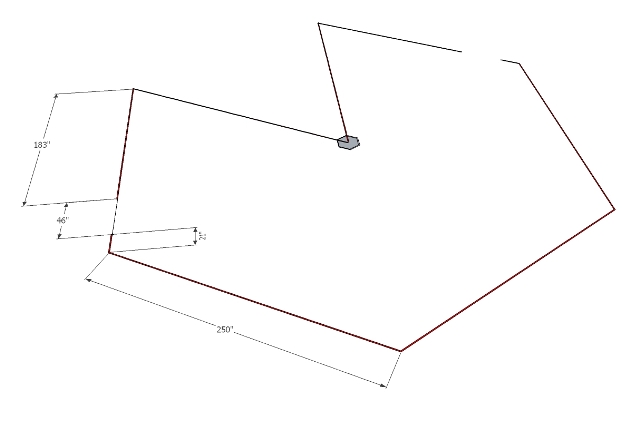
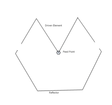
As stated in the below diagrams, I assume that the user knows the geometry of a hexagon. The Reflector has 3 sections of 250″ and two smaller ‘tail’ sections of 21″ each.
Therefore the total Reflector length
= (250 x 3) + (21 x 2)
= 792 “
One leg of the driven element consists of full 250″ piece and a longer ‘tail’ of 183″.
Therefore the total Driven element length of one leg
= 250″ + 183″
= 433″
Yes the total Driven element (433″ x 2) = 866″ is longer than the total reflector length. This is normally the case with the broadband hex beam.
The tail spacing is also critical for the tuning of the Broadband Hex beam and I have left a spacing of 46″. The two tails were connected using plastic ‘fishing rope’. The insulating material is not that critical at 7 Mhz. Therefore don’t hold the project because you don’t have certain brands of rope in your country.
For the elements, I used an insulated stranded copper wire of 9 wires of 0.3mm diameter.
I should also mention here that I have started with a total reflector = 828″ and Driven = 876 as stated in G3TXQ’s web site for #16 wire. But with the wire thickness, insulating, height above ground and other properties, the length of each element can change significantly. After 2 days of trimming and tuning, I was able to achieve the above mentioned lengths for my design which is at 405ft at the moment.
When the 30m element was added to the same feedpoint, the above SWR went up and the antenna resonance has also got shifted. 30M SWR was around 2.5 in the wanted band. But after separating the feedpoints and trimming, the SWR is under 1.4 at 10.110 which is quite impressive. I lost a bit of SWR bandwidth on my 40m after adding the 30m element. But the CW portion of 40m is still 1:1 which is quite good. On 7060, our Sri Lankan rag chew frequency, the needle slowly tries to deflect, and that’s it. What more you can ask from an antenna 
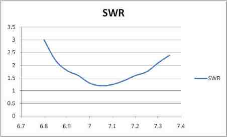
Measured SWR performance : It is clear that the SWR is much better than the classic hex beam across the wanted 40m band. Above is the result of an antenna analyzer. But the real result at the radio is much better and I don’t see the SWR needle moving from 7010 till 7120. Quite impressive
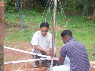
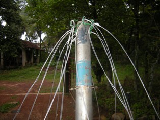
The spreaders
Each spreader has a 16 1/2 ft tapered fiberglass pole and a 6ft of 1″ x 1″ Aluminum ‘L’ section of 3mm gauge. Other materials can also be used. My method was implemented since I only had 16 1/2′ fiberglass poles. The spreaders were supported at 2 places . This makes a solid spreader with minimum sagging.
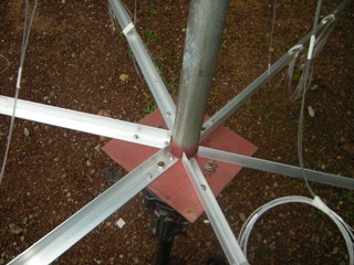
Base Plate
This is a 4mm GI plate. ‘L’ shaped Aluminum bars are connected using nut and bolts. The centre pole is a 1 1/2 inch GI pipe welded to the plate. At 7Mhz you should not worry too much about placing small amounts of metal in the structure. This is required for a stronger construction.
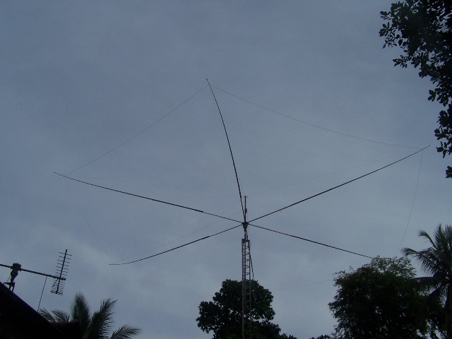
On the air results
After installing the hex beam at 40ft, I was able to work few YB0 stations on 40m using just 50W. Thereafter worked a VK stn and got 59. Later in the night I worked YV5JGO Venezuela and K1IM. Dxing on 40m doesn’t look that difficult anymore
Same results on 30m too. I worked ZL and W’s just after 2 days after putting the 30m element up. This is all with 100W or less using solar powered station. Now I am fully available on 30m. If you need Sri Lanka on 30m, please contact me. I will try my best to give you a contact.
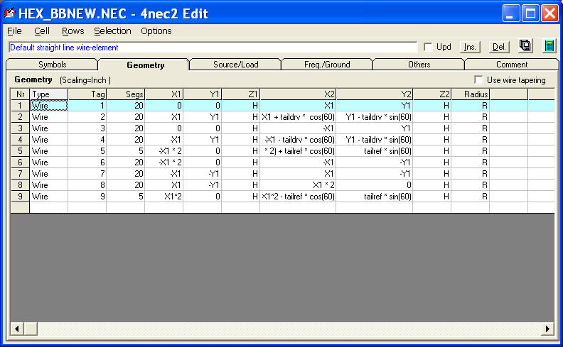
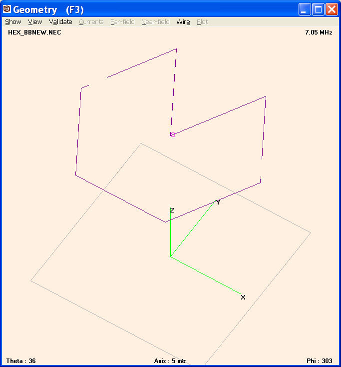
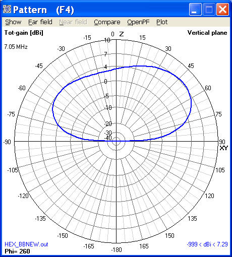
I also ran a few iterations of NEC-2 modeling using 4nec2. I have included a little bit of maths in order to easily scale the design for other frequencies. For the sake of academic interest, I will list some outputs below. But my practical results are somewhat away from the NEC predictions. If you are seriously interested to see my NEC-2 files, please email me via qrz.com. I will send you a copy.