2m Long Boom Yagi
13el Long Boom Yagi for 2m Terrestrial and LEO SAT operation
1000+ already viewed!
Article Summary
I had this antenna for a long time from 1994 to 2000. But it was broken into 2 pieces during an improper mast mounting exercise. I wanted to repair and modify it for further service. I have used that for direct QSOs with the stns in Colombo (50km away) and also to access some of the Indian repeaters in South India.
Article Highlights
- Design and Construction
- The Trans Match construction
- Results

Kamal Edirisinghe
4S7AB / KA5MAL
Author Jan 2000
Having More than 35 years of experience in the Field of Amateur Radio, I have published many articles in prestigious international publications like, QST, CQ-DL, NCJ, Six-News etc.. Here in this web site, these write-ups are intended to give you knowledge about my designs and projects related to the hobby. The articles about foreign HAM activities are intended to share my experience.
- Full Solar Powered Radio Station
- SO2R and Multi-Multi Compatible
- Operate on All Bands/Modes/SATS
- DXCC #61,271
- IOTA AS-003, CQ-22, ITU-41
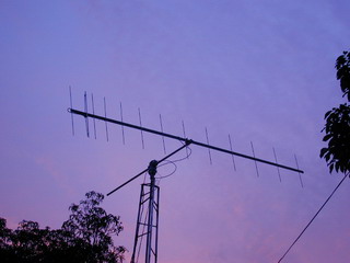
This 2m antenna design is appearing in almost every ARRL handbook. But I have done 3 modifications for my requirement.
1) Used a square 2″ x 1″ aluminum boom which makes it easy to install the elements in correct geometry.
2) Added an extra director which was possible with the 20ft boom which is readily available in the market
3) Recalculated and retuned for 145.600 Mhz
It is installed on a Yaesu G5500 AZ/EL Rotor for Sat tracking. On the other side of the mast, I have a 70cm yagi. All good for Satellite operation
I have used a T-match in place of the much simpler gamma match . I have tried the gamma match but the SWR bandwidth was very narrow. The T-match SWR bandwidth for <1:1.7 is about 1.5 times that of the gamma match.
Many hams think that the T match is difficult to construct. There is a truth in that. But once you get hold of the design, it is a little extension from the gamma match.
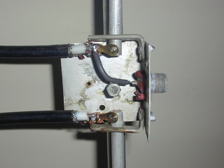
I have used LMR400 hard line for the 180° phasing network. The inner conductors are attached to the T match bars using copper solder lugs and connected using self tapping screws to the 3/8″ aluminum pipes. These pipes are supported on a PVC bracket.
The Feed point arrangement for the T match is in the picture on the right side. Antenna is tuned for 50Ω + 0j feed point impedance.
The T match rods are connected to the driven element using 1/2″ aluminum bracket. The adjustments are being made and the two nuts are tightened for better connectivity. Sometimes it is important to sandpaper the inner side of this bracket for optimum connectivity.
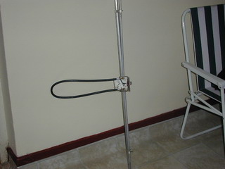
The Total T match can be removed from the yagi and separated for proper weather shielding and tightening. This also helps to prevent the driven element arrangement getting damaged while installing the other elements.
Once the whole set of antennas are installed in place, the driven element can be installed and tuned.
So far the antenna is working fine for terrestrial contacts. The main feeder is 1/2″ heliax . The plan is to improve this for satellite work and maybe for moon bounce at a later stage.