Article Summary
The 70cm yagi design was based on the famous design that appear in the ARRL antenna handbook. But the element lengths were modified slightly in order to obtain the feed point impedance that I wanted.
Article Highlights
- The Design and Construction ideas
- The T-Match
- SWR measurements

Kamal Edirisinghe
4S7AB / KA5MAL
Author Jan 1998
Having More than 35 years of experience in the Field of Amateur Radio, I have published many articles in prestigious international publications like, QST, CQ-DL, NCJ, Six-News etc.. Here in this web site, these write-ups are intended to give you knowledge about my designs and projects related to the hobby. The articles about foreign HAM activities are intended to share my experience.
- Full Solar Powered Radio Station
- SO2R and Multi-Multi Compatible
- Operate on All Bands/Modes/SATS
- DXCC #61,271
- IOTA AS-003, CQ-22, ITU-41
The computer modeling using YO software shows that the feed point is around 18 + 20j. But it is possible to raise the impedance to about 24 + 10j by shortening the first director of this design by 3mm. That is exactly what I did. Because my initial try was to go for the gamma match as the 2m yagi. But then I found that the SWR bandwidth is too low with the gamma matching and wanted to try the T match as described in the ARRL handbook. The exact dimensions were used but the only exception was that I used RG213 cable for the impedance transformer instead of the RG141 mentioned in the book. This yields a slightly shorter cable length corresponding to the velocity factor change.
For all the detailed construction details, please refer to the ARRL Antenna handbook.
The T Match
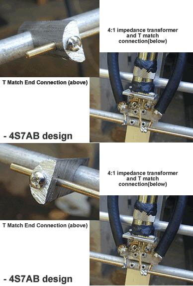
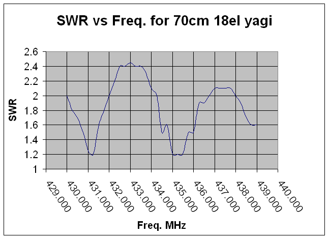
I have used a T-match in place of the much simpler gamma match . The gamma match was tried but the SWR bandwidth was very narrow. The T-match SWR bandwidth for <1:1.7 is about 1.8 times that of the gamma match. Also a flat SWR response was obtained in the 433.5 – 438.0 MHz range with the T match.
Many hams think that the T match is difficult to construct. There is a truth in that. But once you get hold of the design, it is just a little extension from the gamma match.
I have used RG 213 for the 180° phasing network. The inner conductors are attached to the T match bars (3mm brass welding rods) using copper solder lugs and connected using self tapping screws to the 3/8″ aluminum pipes. See the above picture.


